
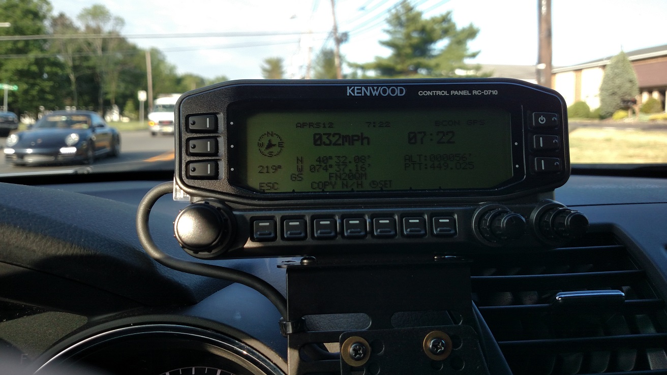
I have a Kenwood TM-V71a that I upgraded with the RC-D710 head for full APRS functionality. At the time I got this the RC-D710 head did not come with an integrated GPS, so I had built a breakout box that took power from the RJ45 cable and directed it to a BR-355 GPS Puck. This was a pretty ugly solution with too many wires, but it worked.
After reading a few foreign websites that showed people adding GPS chips inside, I took the idea and modified it a bit. I mounted my GPS puck directly on the back of my remote head and tapped into the motherboard for power and GPS signal. My primary inspiration was here, but I changed it up a little.
Steps:
-Remove the 2 screws on the lower back of the head.
-Remove the back cover by pulling bottom first
-Cut the GPS cord – give yourself at least 8″ of cord connected to the GPS to play with, you will trim it later.
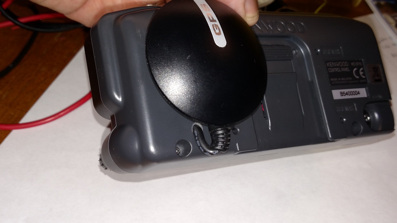
– Drill a hole in the back of the unit as shown and fish the GPS wire through.
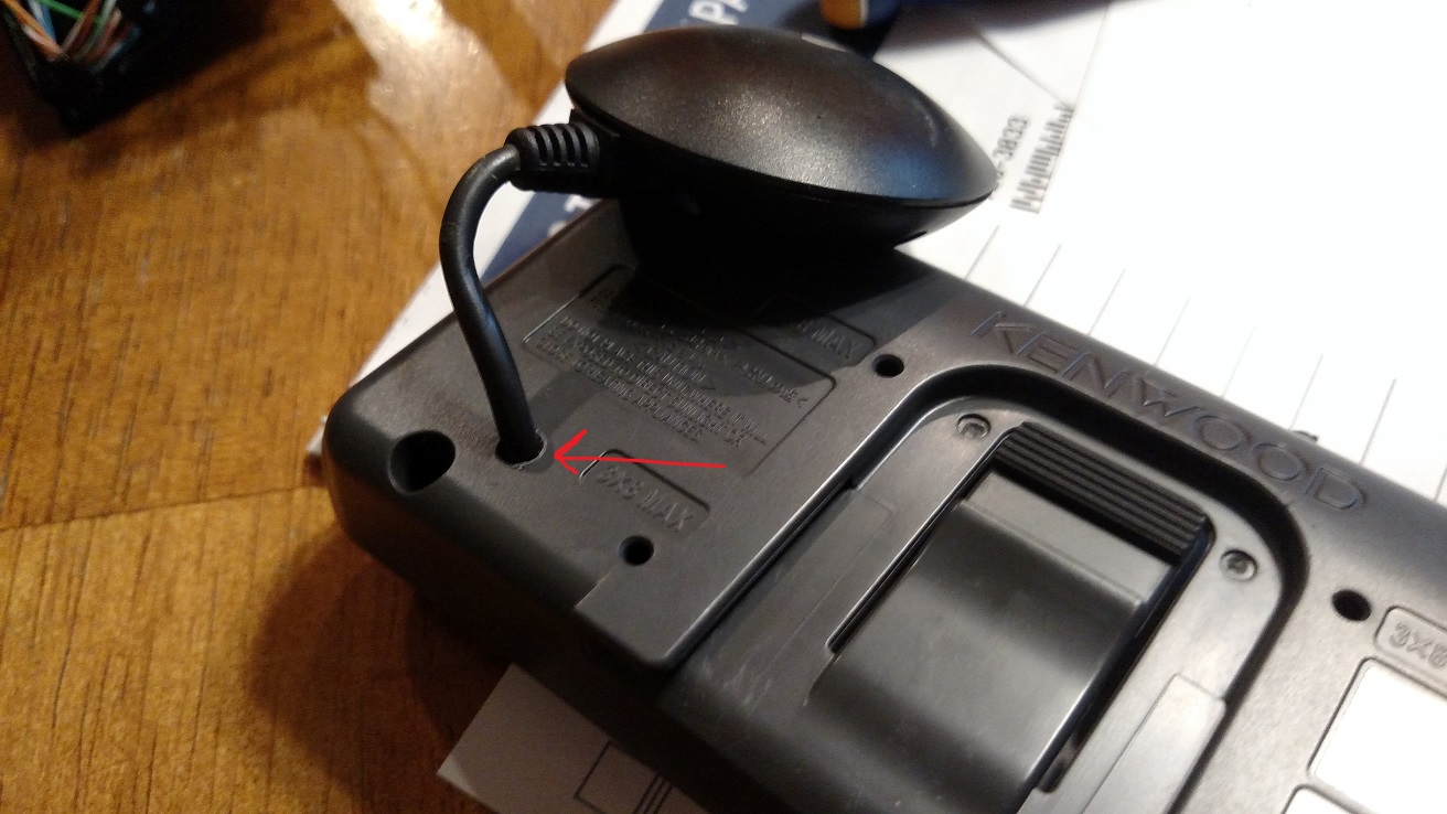
-Attach the GPS Puck to the back of the unit with double sided foam tape, being careful not to impede the track mechanism for the base. Put aside the back/GPS for now.
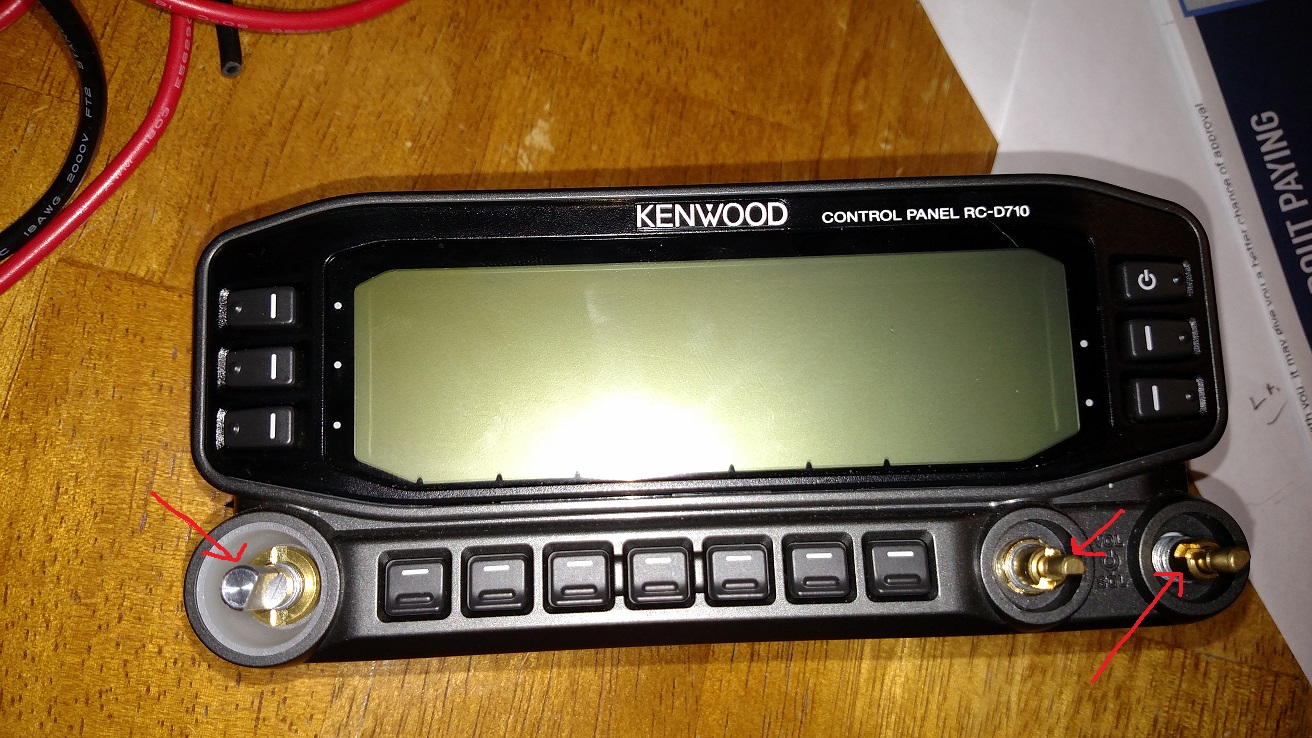
-Remove the plastic knobs carefully from the front.
-Remove the round nuts holding the metal knob shafts onto the case. I used a long nosed pliers and small flat head screwdriver to turn them
-Gently remove the thin plastic sheet covering the circuitry
-Put the unit screen-down on a soft cloth.
-Remove the 2 screws on top of the circuit board holding it in place
-Gently pull directly up on on the ‘knob shaft assemblies’ that are attached to system board. The should come off easily. PAY ATTENTION TO WHERE EACH GOES so you can be sure to put them back on the right place. Sorry I didn’t take a pic, but here is a picture from the site above.
-Trim the GPS wires, but leave some play so the cover can easily close. Better to have a little wire coiled than to cut them too short.
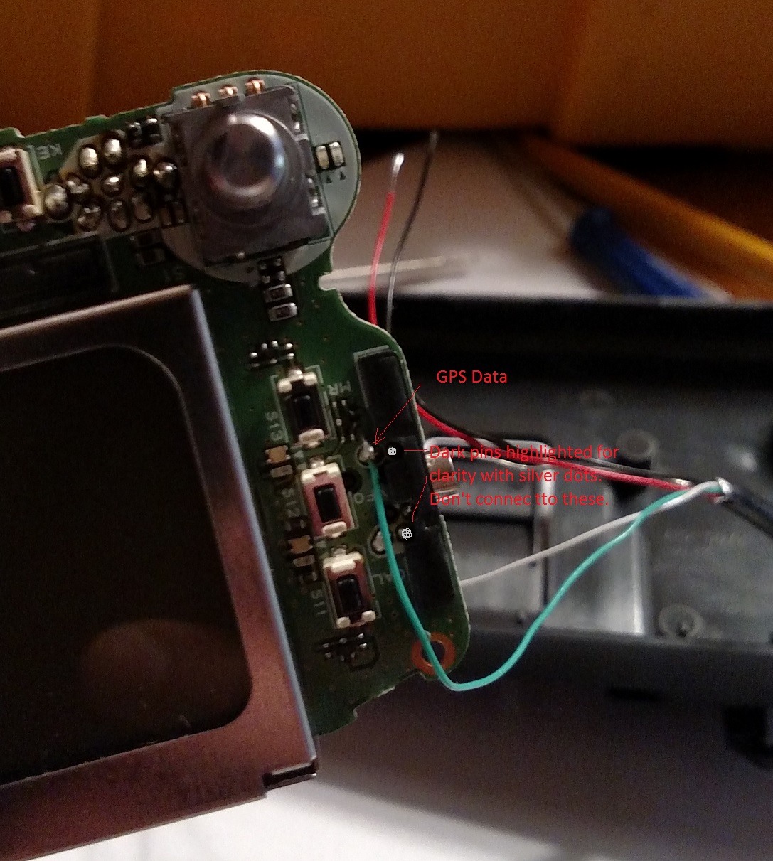
-Solder the GPS Data wire (Green on my BR-355) to the point highlighted below on the screen-side of the board. .
-Put the board back into the case, being careful to route your GPS data wire where it will not be pinched.
-Attach the +5V line as shown here. On my unit the red wire is +5v,

-Attach the black and white grounds for power and GPS signal to the point shown”
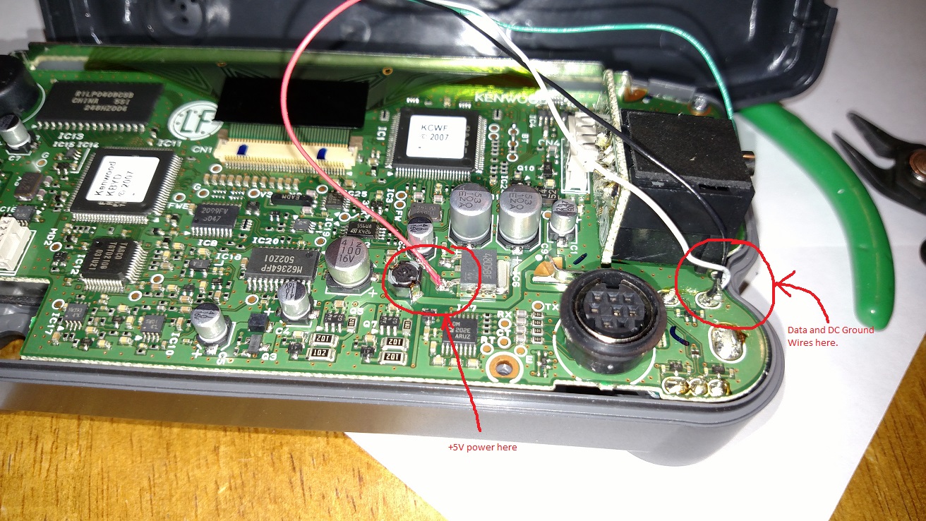
-Reassemble the radio in reverse order, being careful to route your wire where they will not be pinched.
-Test it out! Mine worked correctly the first time. This is a rarity for me. 🙂
3 comments
1 ping
Nice job! Glad I inspired you and the work succedeed well! 73 de Adrian YO3HJV
I own two D710s, so I ordered two RYN25DI GPS modules off eBay from China for $31 delivered and followed the example from the German site. Works like a charm. One less cable and I am no longer limited to my Nuvi 255W.
I used my 3D printer to print a small sheet of ABS to place between the circuit boards.
AC7KJ
Thanks for this page OM! I did the hack on my D710 today. My GPS is a Deluo Universal. It worked fine following your procedure. 73
-Scott N3SW-
[…] followed the instructions posted by W2DHS at https://www.w2dhs.com/2016/07/07/adding-gps-to-a-kenwood-rc-d710-and-possibly-tm-d710 for attaching the external GPS receiver to the back of the D710 control head and hardwiring it to […]