
Welcome to the site. This is the Amateur Radio site of Dave Santoro, W2DHS. I will generally post items that I think may help other hams. This isn’t a blog that I will be updating on any particular schedule.
Nov 15
New Home, New Shack!
Jan 18
Go Box is Progressing…
Got a little work done tonight, getting excited to permanently attach everything and wire it up! The bottom is a 1U drawer from Amazon. I will post a complete parts list toward the end of the project.
Jan 03
3D-Printed 1U Panel for Go-Box
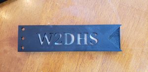
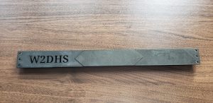
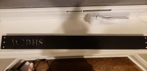
On my new Go-Box, the plan is to have the top 1U slot set up for miscelaneous switches, lights and outlets, so I needed a blank panel to start with. I also wanted to 3D print it so that I could integrate my callsign. I quick search on Thingiverse yielded this blank panel, which I popped into TinkerCad and added my callsign.
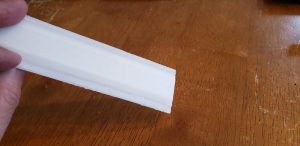
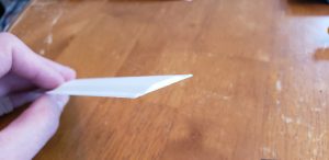
Santa brought an amazing Creality Ender Pro 3 D printer for Christmas, and I immediately put it to work printing this panel. It came out pretty well, but the finish was uneven so I decided to sand and paint it with Rustoleum Hammered Black spray paint. I also designed and printed a thin white diffuser for behind my callsign. I will extend the RGB lighting that I plan on using inside to this panel so that my callsign will be backlit. Of course this is a bit of a frivolous for-show detail, and it will be on a switch so as to save power most of the time.
 The Diffuser
The Finished, painted panel with light diffuser attached.
Jan 03
New project – Portable Go Box.
I have started planning for a new go box for use in Emergency Communications (I am in ARES and CERT) and for Field Day, SOTA, and other outdoor operations. I have based my plans on a few different boxes seen around the internet. Here are the key aspects I have settled on:
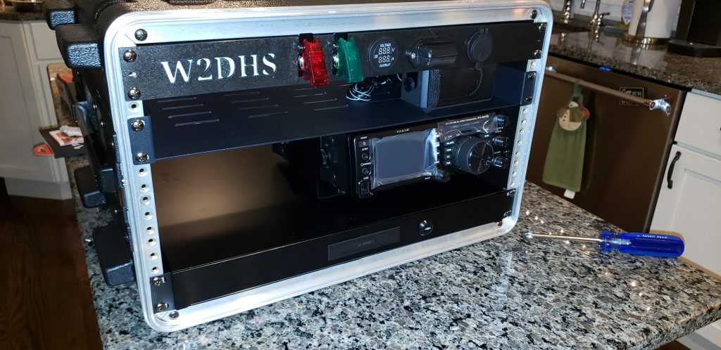
- Primary rig – Yaesu FT-991a (This is HF, 2m and 70CM)
- PC – Microsoft Surface Pro 3 Tablet
- Built in a 6U Rack Case
- 1U Drawer for storing keyboard, mouse, mics, etc.
- 3D-printed 1U “blank’ dedicated to lighting, and bulkhead USB, Power Meters, Powerpoles. This will have my callsign backlit with internal switched LEDs.
- I would like to have the tablet PC fold-out similar to how this guy did it. I really like his setup.
I will post updates periodically.
Jul 31
Great podcast
I haven’t posted much lately due to a busy schedule, but I want to be sure to help spread the word about an excellent podcast I have come across. The description on their site is spot-on:
Ham Radio Workbench deep dives on making, DIY, electronics, and technical topics of interest to the amateur radio operator. Your hosts George KJ6VU and Jeremy KF7IJZ discuss current developments in ham radio while introducing listeners to a plethora of topics and skills such as test equipment, 3D Printing, Arduino, Raspberry Pi, and more.
I have found 90% of the few dozen episodes I have listened to be highly relevant, technically detailed, interesting, and fun. Each episode is 2+ hours and I have never been bored for a moment. I highly recommend Ham Radio Workbench…. check it out!!
Jul 07
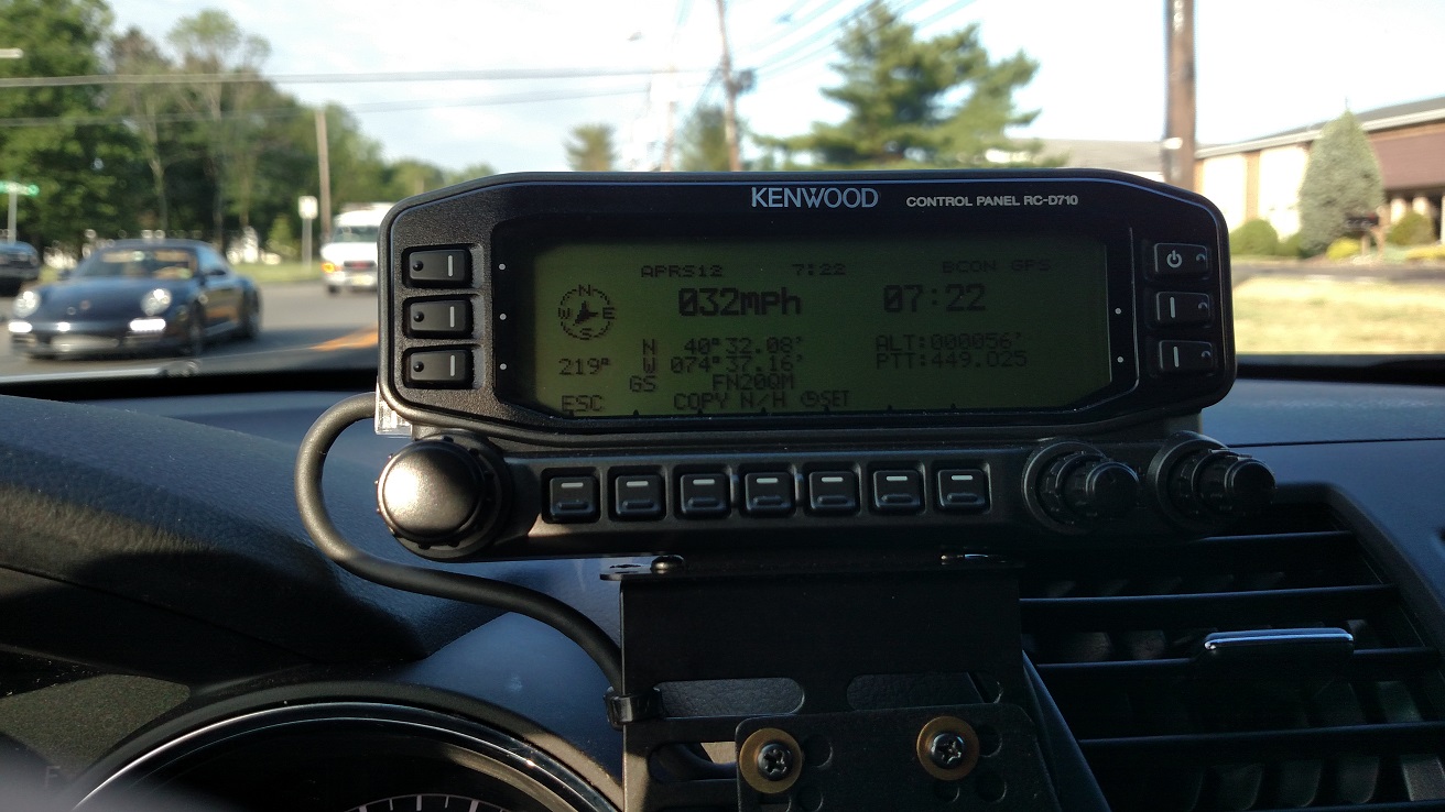
Adding GPS to a Kenwood RC-D710 (and possibly TM-D710)
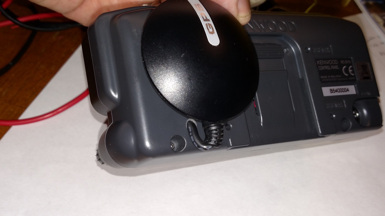
I have a Kenwood TM-V71a that I upgraded with the RC-D710 head for full APRS functionality. At the time I got this the RC-D710 head did not come with an integrated GPS, so I had built a breakout box that took power from the RJ45 cable and directed it to a BR-355 GPS Puck. This was a pretty ugly solution with too many wires, but it worked.
After reading a few foreign websites that showed people adding GPS chips inside, I took the idea and modified it a bit. I mounted my GPS puck directly on the back of my remote head and tapped into the motherboard for power and GPS signal. My primary inspiration was here, but I changed it up a little.
Steps:
-Remove the 2 screws on the lower back of the head.
-Remove the back cover by pulling bottom first
-Cut the GPS cord – give yourself at least 8″ of cord connected to the GPS to play with, you will trim it later.
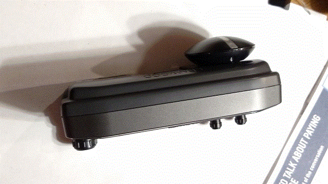
– Drill a hole in the back of the unit as shown and fish the GPS wire through.
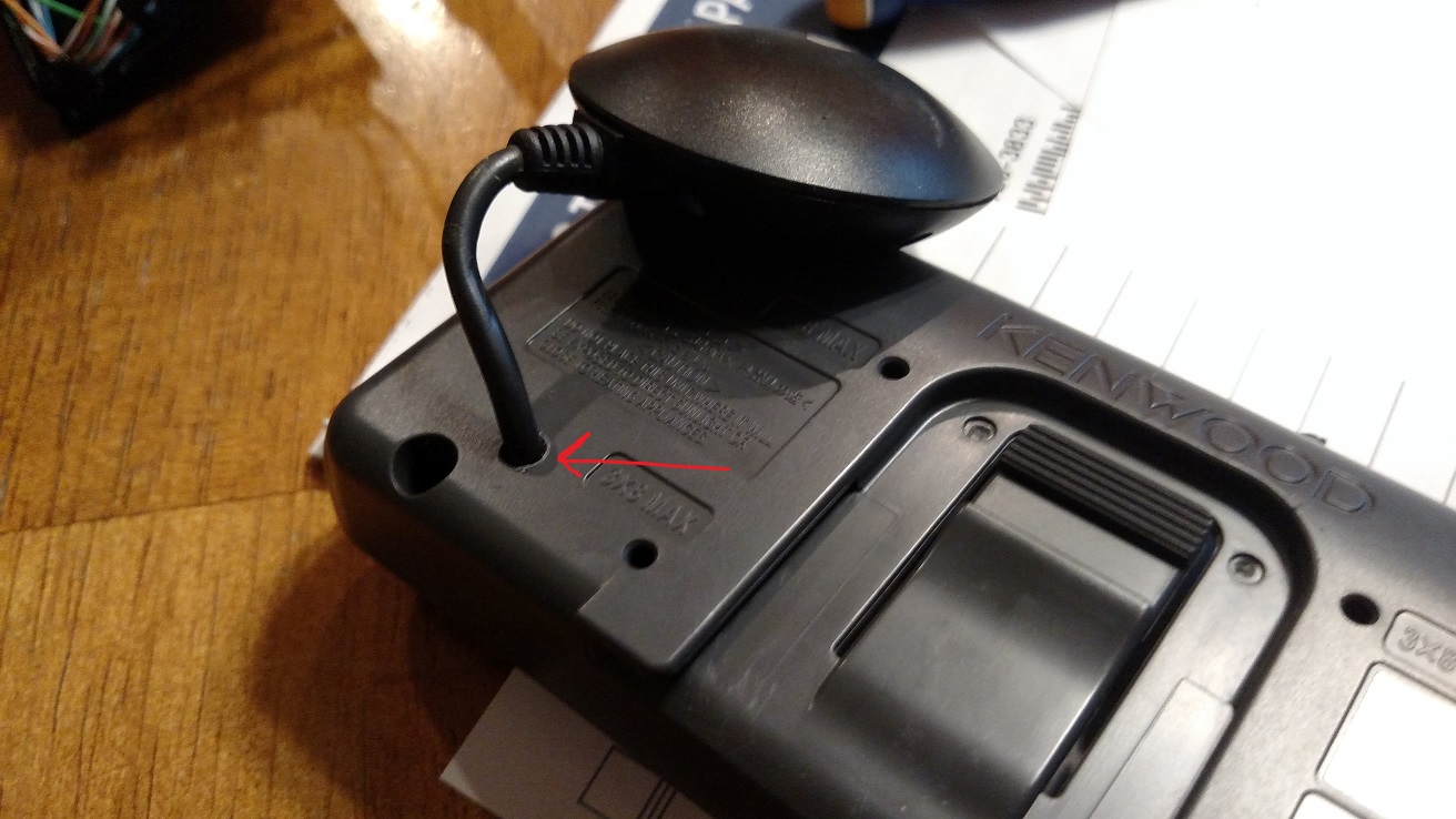
-Attach the GPS Puck to the back of the unit with double sided foam tape, being careful not to impede the track mechanism for the base. Put aside the back/GPS for now.
-Remove the plastic knobs carefully from the front.
-Remove the round nuts holding the metal knob shafts onto the case. I used a long nosed pliers and small flat head screwdriver to turn them
-Gently remove the thin plastic sheet covering the circuitry
-Put the unit screen-down on a soft cloth.
-Remove the 2 screws on top of the circuit board holding it in place
-Gently pull directly up on on the ‘knob shaft assemblies’ that are attached to system board. The should come off easily. PAY ATTENTION TO WHERE EACH GOES so you can be sure to put them back on the right place. Sorry I didn’t take a pic, but here is a picture from the site above.
-Trim the GPS wires, but leave some play so the cover can easily close. Better to have a little wire coiled than to cut them too short.
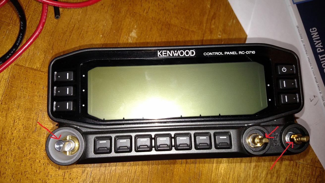
-Solder the GPS Data wire (Green on my BR-355) to the point highlighted below on the screen-side of the board. .
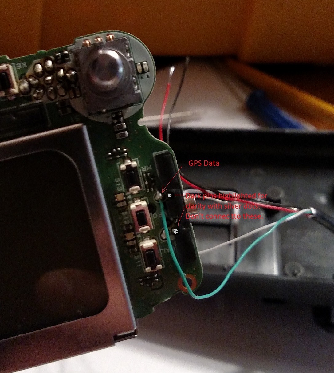
-Put the board back into the case, being careful to route your GPS data wire where it will not be pinched.
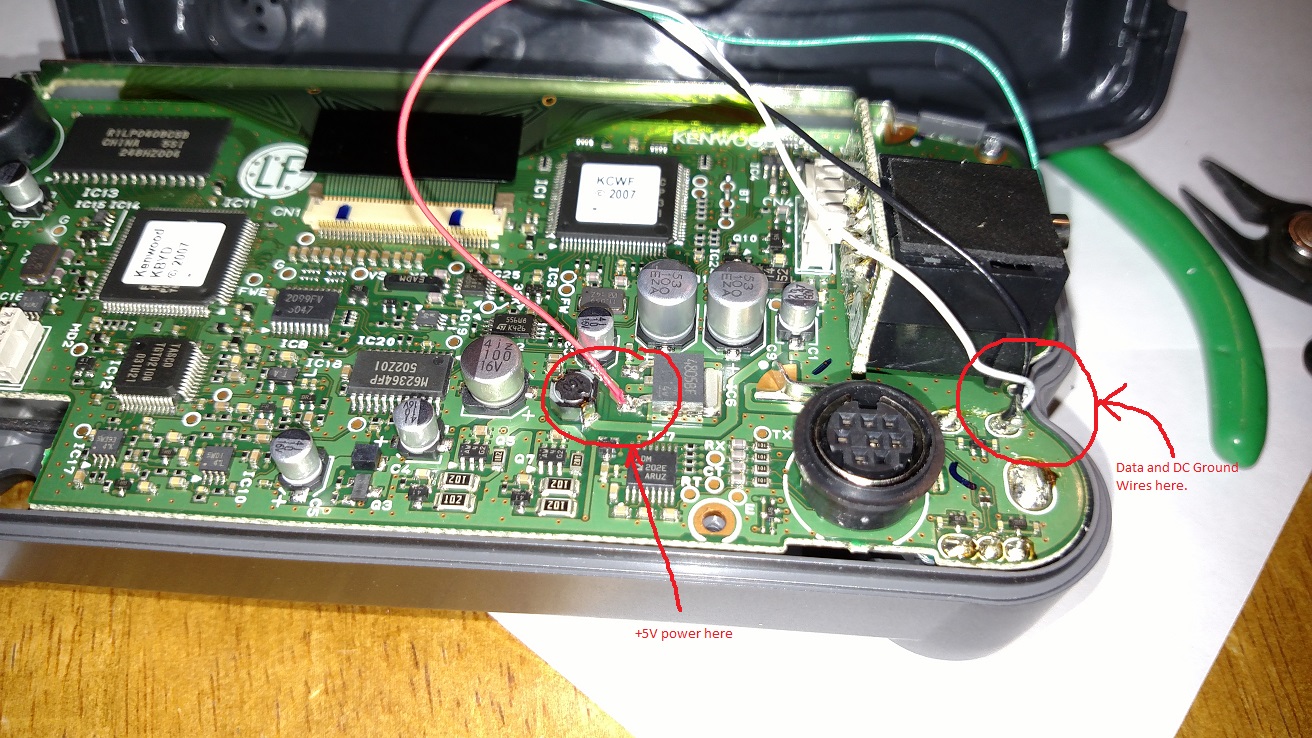
-Attach the +5V line as shown here. On my unit the red wire is +5v,

-Attach the black and white grounds for power and GPS signal to the point shown”
-Reassemble the radio in reverse order, being careful to route your wire where they will not be pinched.
-Test it out! Mine worked correctly the first time. This is a rarity for me. 🙂
Dec 13
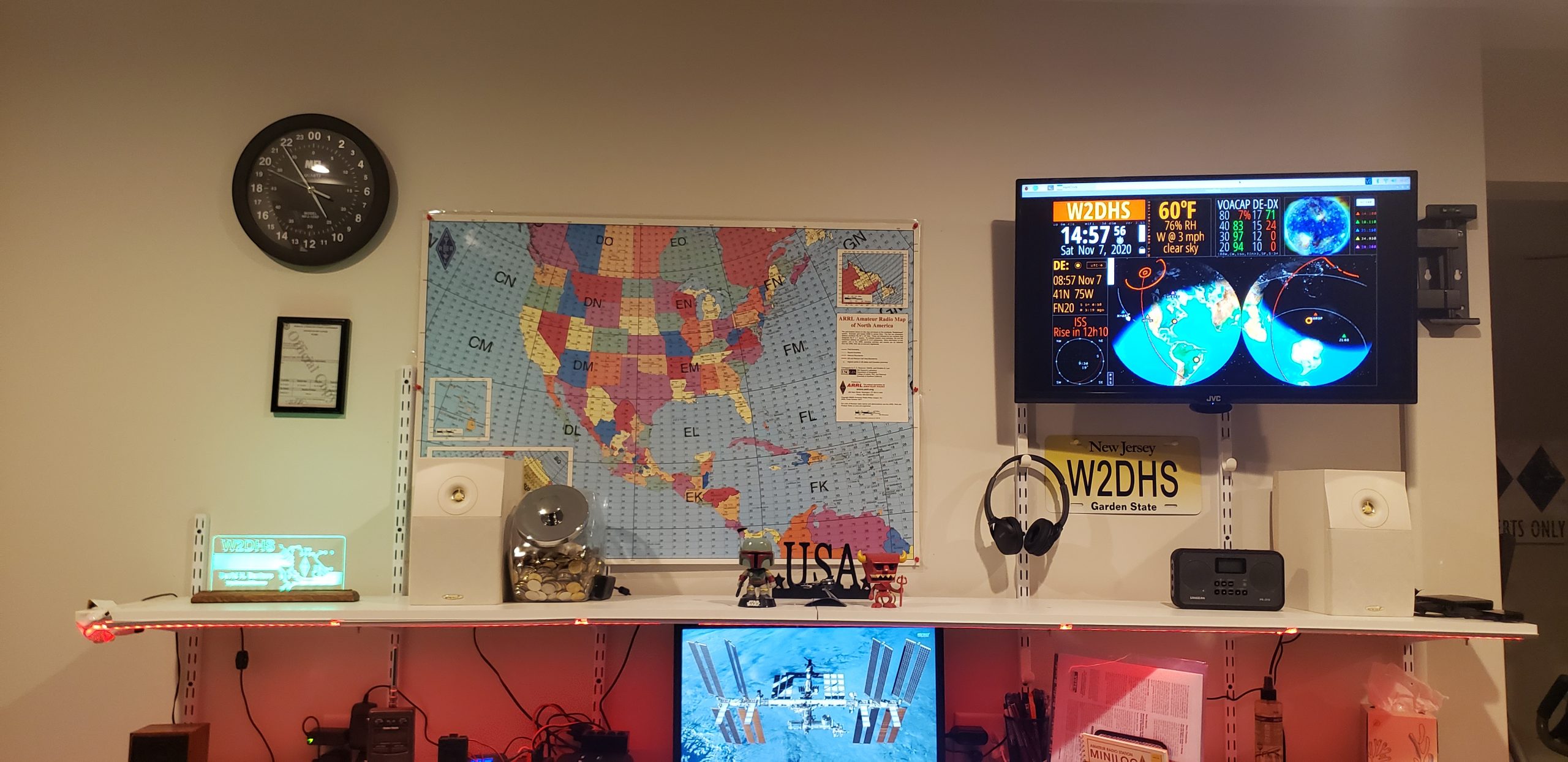
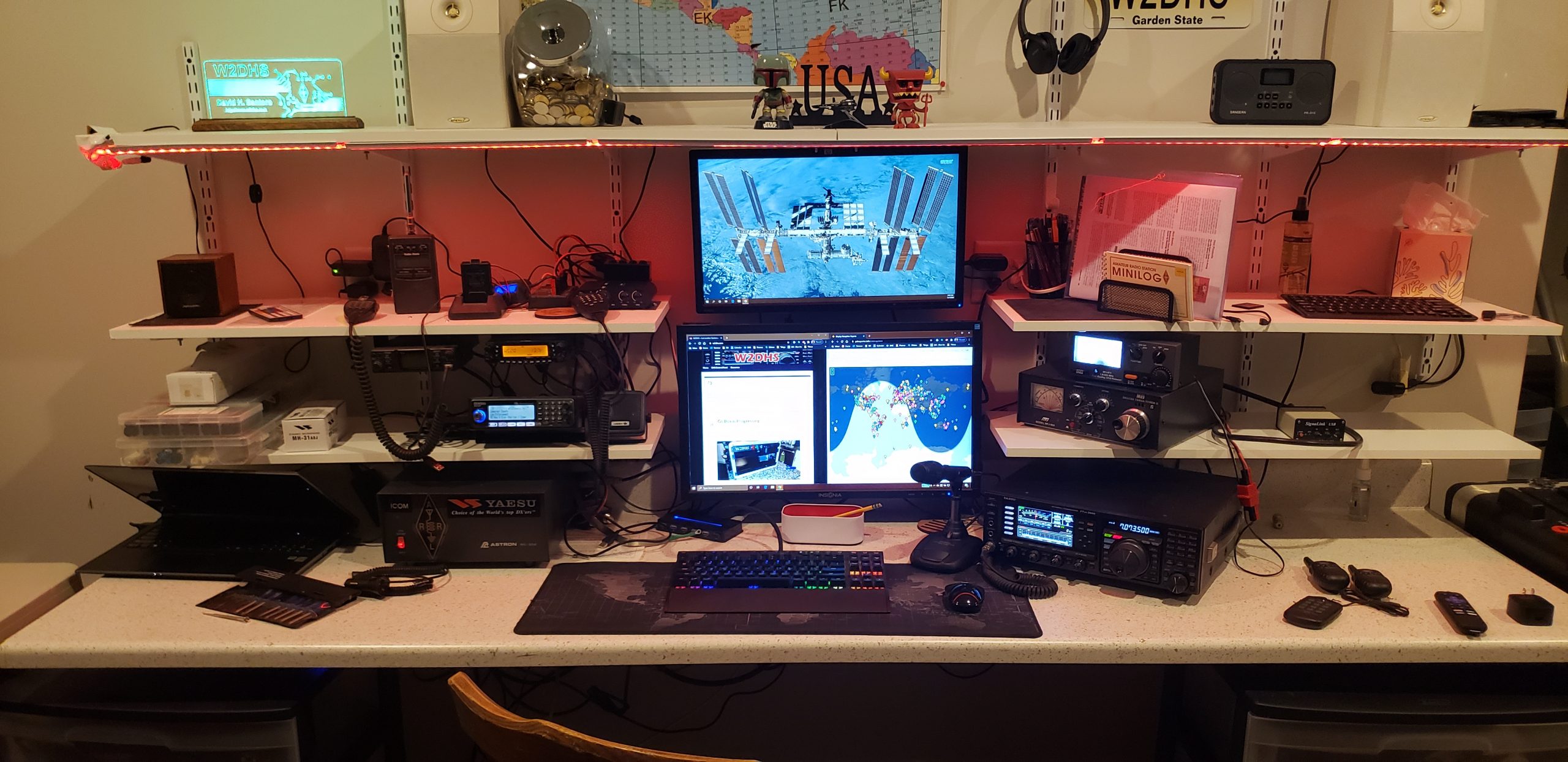
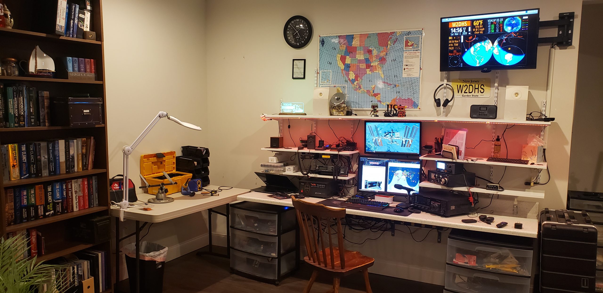
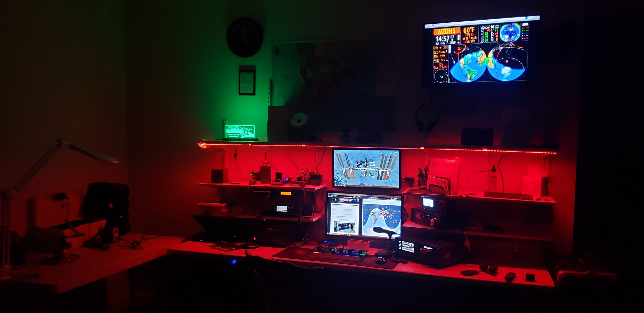
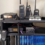
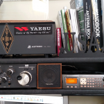
My Shack Configuration.
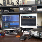
I have a fairly modest shack compared to others I have seen online, but it gets the job done. I grabbed a corner in our family room an brought up an old cheapie desk that we had stored away. I built the shelves out of MDF from Home Depot.
Here is my current gear:
HF:
- Yaesu FTDX3000
- MD-10 Desk Mic
- MFJ-969 Versa Tuner
- G5RV Jr. Antenna in my attic
VHF/UHF:
- TYT TH-9800 Quad Band Transceiver for day-to-day use
- Icom IC-281h transceiver is in service as a data-only radio
- Signalink USB interfaces the data radio to the PC
- Arrow OSJ-146/440 J-Pole Antenna for the Data Radio
- Arrow OSJ-146/440 J-Pole Antenna for the TYT Radio
Monitoring:
- Radio Shack Pro-652 Digital P25 Scanner
- Realistic 40-1250C External Speaker
- 25 year old Radio Shack Discone scanner antenna
Mobile:
- Yaesu VX-5R HT
- Baofeng Uv-5R as a spare or for use in rough situations
- Radio Shack Pro-95 Portable Scanner
Mar 02
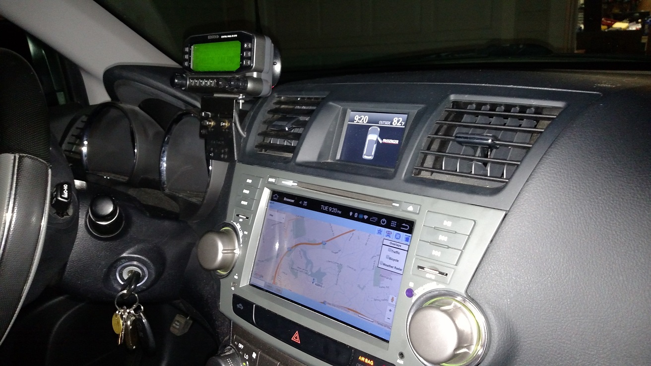
2011 Highlander, Kenwood TM-V71A amateur transceiver installation
While I had permanently installed my scanner and dual band antennas (and written about it) last year, I have been thinking hard about how to mount the radios, remote head, power switches, mic, and speakers on the interior.
I spent the last year testing a few temporary scenarios, including most recently having the radio just sitting the on the floor under the driver seat wit the remote head on a cup holder mount. It just too messy and I wanted something much more integrated with the car.
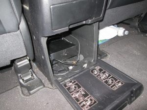
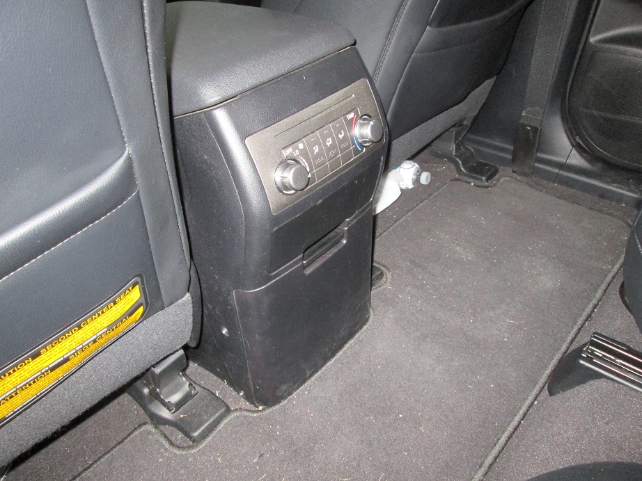
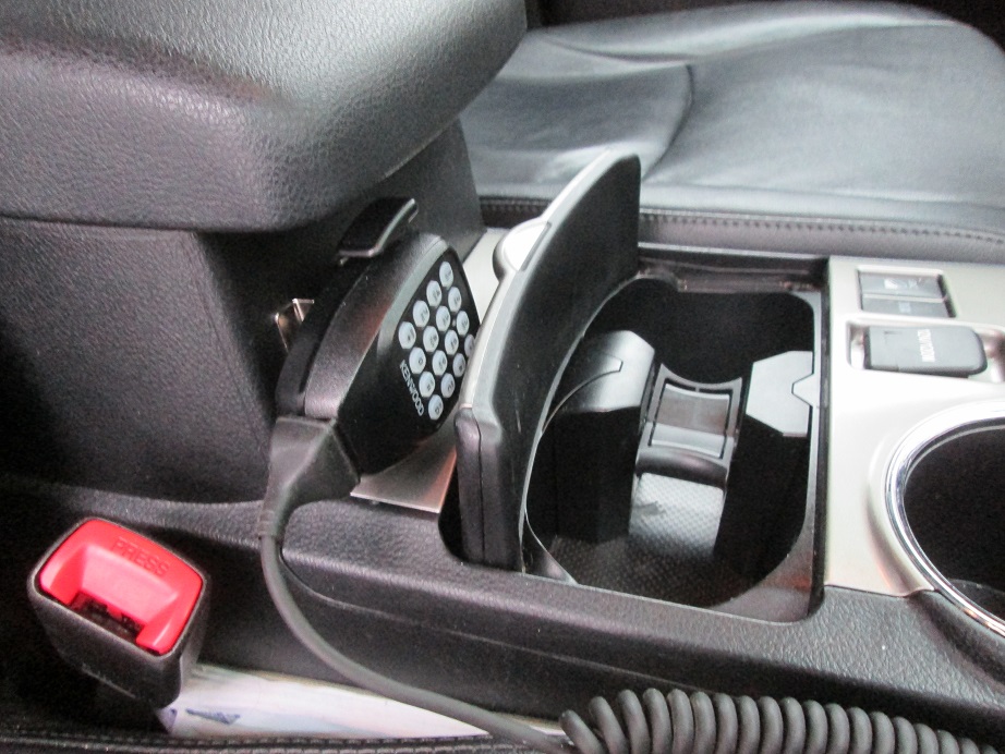
I struggled for months deciding where I wanted to permanently mount the radios. Under the seat was a good thought but with the rear heater vent under there, and combined with the in seat ‘butt-warmers,’ I was very concerned about heat issues with my radios. One day a few weeks ago, it struck me that I actually I have a cavernous space available to me under the center armrest/console. There is a rear-accessible compartment that is used to hold the swappable middle row center cupholder console and mini center seat. I only have used the little console once in three years. I just had to leave the unused console in my garage, and the space was mine to use as I see fit.
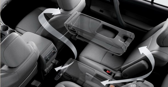
Here you see this compartment opened and closed. Perfect. (Radios are not yet permanently mounted.)
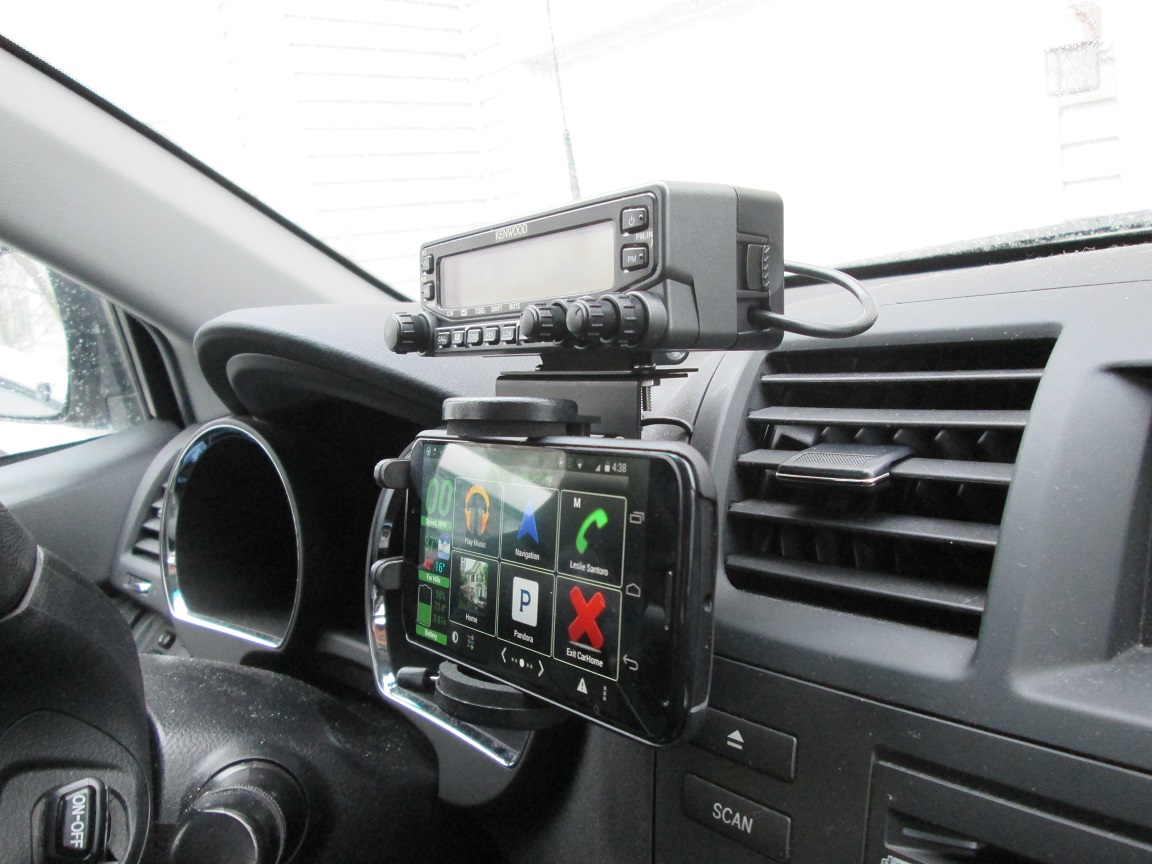
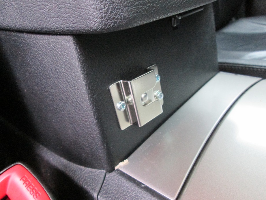
I also brought a Pro Fit custom mount that allows me to mount my Radio head and cell phone holder on my dash immediately left of the center driver vent.
The speakers for scanner and ham rig are mounted thusly:
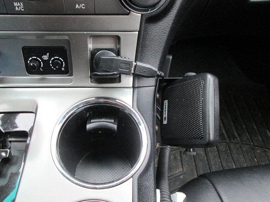
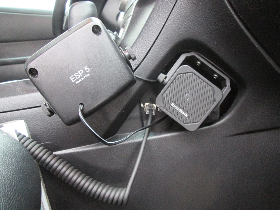
All wiring (power, speaker, mic, remote head) is invisibly routed behind the dash and through the armrest console to the radio compartment. You can see that for the scanner I used a basic small Radio Shack extension speaker which fits nicely in the recessed side ‘cubbyhole,” while I used the Uniden SEP-5 speaker for the Kenwood dual band rig, screwed directly into the side of the console with black screws. It hurt to do this, but I saw no other way.
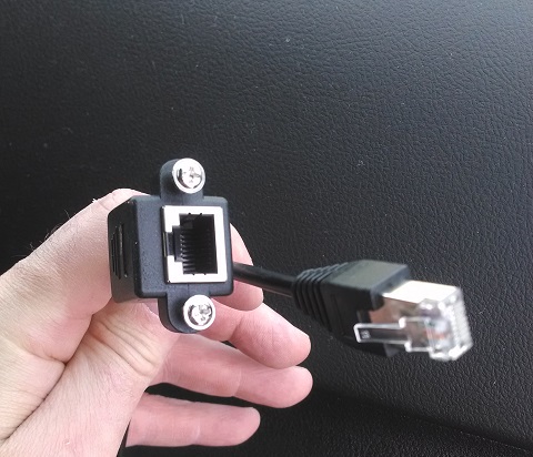
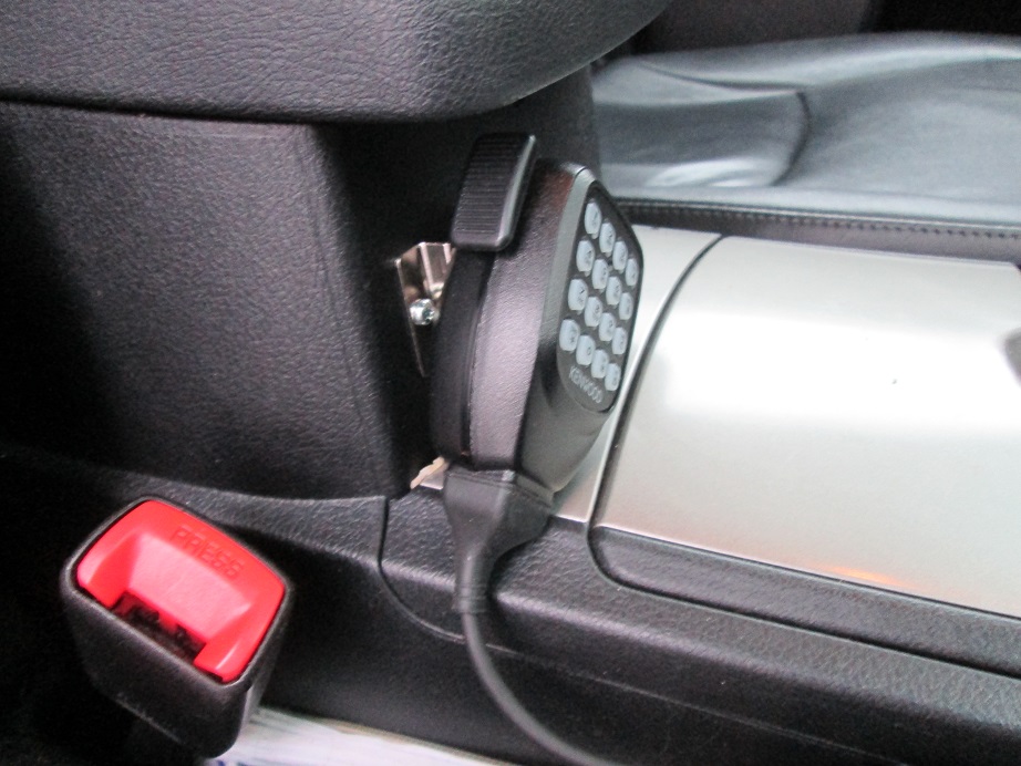
If you look at the picture above. you can see the Kenwood microphone plugs into an RJ45 panel mount jack that I mounted in the little cubby hole behind the smaller speaker.
I used this shielded panel mount pigtail from seller cablesonline.net on eBay :
Then the mic holder was mounted to the front of the armrest console.
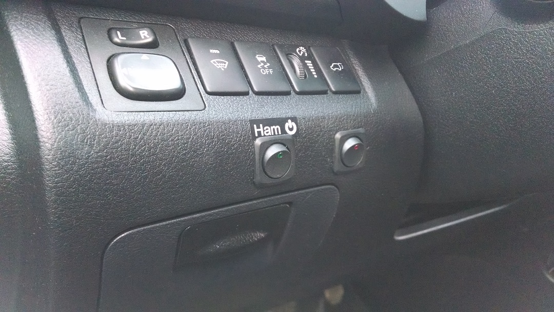
Finally, I put switches int he left side of the dash to control the power for 1) all the ham gear, and 2) the TinyTrak III tracker for when I want to use the dual bander without APRS tracking. (the label is temporary. I want to make it look more consistent with the fonts and styling of the OEM switches later.) The switches are in tight using friction. I drilled a slightly-too-small hole then uses a razor to enlarge it until I could force in the switches.
I will post again when I finally mount the Radio Chassis in the compartment. I have a repair pending that I need to complete first.
Dec 26
Look what Santa Brought!
 I got a nice call sign plaque for my shack. We got it from ProjectGM and it came out great.
Credit for this fantastic design goes to Richard Graves!
- 1
- 2
Recent Comments